


The main differences between RS-232, RS-422 and RS-485
| Designation | RS-232 | RS-422 | RS-485 |
| Transmission Type | Full-dupleks | Full-dupleks | Half-duplex (2 cables), fill duplex (4 cables) |
| Maximum distance | 15 meters at 9600 bits / s | 1200 meters at 0.1 - 10 Mb/s | 1200 meters at 0.1 - 10 Mb/s |
| Engaged connectors | TxD, RxD, RTS, CTS, DTR, DSR, DCD, GND* | TxA, TxB, RxA, RxB, GND | DataA, DataB, GND |
| Topology | Point-to-Point | Point-to-Point | Multipoint |
| Max number of connected devices | 1 | 1 (10 devices in receive mode) | 36 (with relay more, usually up to 256) |
* For the RS-232 interface, it is not necessary to use all cable contact pins. Usually TxD, RxD data lines and GND ground wire are used, the other pins are necessary to control the data flow. You will learn more later in this article.
The information sent through the RS-232, RS-422 and RS-485 interfaces have a protocol structure, for example, the Modbus RTU protocol is widely used in industry.
Description of the RS-232 interface
The RS-232 interface (TIA / EIA-232) is intended for organizing the transmission and reception of data between a transmitter or terminal (Data Terminal Equipment, DTE) and a receiver or communication equipment (Data Data Equipment, DCE) according to the point-to-point scheme.
The RS-232 speed depends on the distance between devices, usually at a distance of 15 meters, the speed is 9600 bit / s. At a minimum distance, the speed is usually 115.2 kbit / s, but there is equipment that supports speeds up to 921.6 kbit / s.
The RS-232 interface operates in full-duplex mode, which allows simultaneous transmission and reception of information because different lines are used to receive and transmit. This is a difference compared to the half-duplex mode, when one communication line is used to receive and send data, which imposes restrictions on simultaneous operation, so in half-duplex mode it is possible to receive or transmit information at one time.
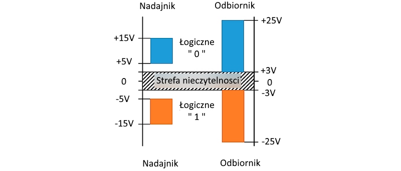
Information via the RS-232 interface is sent digitally via logic 0 and 1.
Logic "1" (MARK) corresponds to a voltage in the range from -3 to -15 V.
Logic "0" (SPACE) corresponds to a voltage in the range from +3 to +15 V.
In addition to two receiving and transmitting lines, the RS-232 has special lines for hardware flow control and other functions.
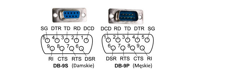
A special D-sub connector is used to connect to RS-232, usually 9 pin DB9, rarely 25 pin DB25.
DB connectors are divided into male - "father" (plug, pin) and female - "mother" (socket, socket).
A special D-sub connector is used to connect to RS-232, usually 9 pin DB9, rarely 25 pin DB25.
DB connectors are divided into Male - (plug, pin) and Female - (socket).

Pinout of the DB9 connector for RS-232
DB9 cabling for RS-232
There are three types of connecting devices in RS-232: terminal-terminal DTE-DTE, terminal-communication equipment DTE-DCE, modem-modem DCE-DCE.
The DTE-DCE cable is called a "straight cable" because the contacts are connected to each other.
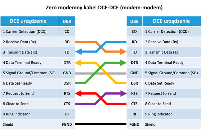
The DCE-DCE cable is referred to as the "zero modem cable" or otherwise a cross cable.
Below are pinout tables for all types of cables listed.
Pinout of the simple DB9 cable to RS-232
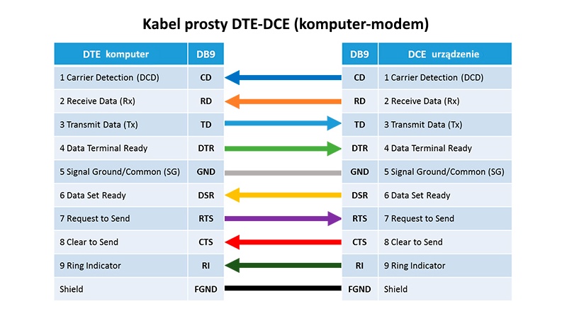
| DB9 | DB25 | Designation | Sign | Description DE |
| 1 | 8 | CD | Carrier Detect | Trägererkennung |
| 2 | 3 | RXD | Receive Data | Empfange Daten |
| 3 | 2 | TXD | Transmit Data | Daten übermitteln |
| 4 | 20 | DTR | Data Terminal Ready | Datenterminal bereit |
| 5 | 7 | GND | System Ground | Systemmasse |
| 6 | 6 | DSR | Data Set Ready | Datensatz bereit |
| 7 | 4 | RTS | Request to Send | Anfrage zum Senden |
| 8 | 5 | CTS | Clear to Send | Zum Senden freigeben |
| 9 | 22 | RI | Ring Indicator | Ringanzeige |
For connection with RS-232 devices you usually need only 3 connections: RXD, TXD and GND, however some devices need all 9 pins to support data flow function.
The structure of transmitted data in RS-232
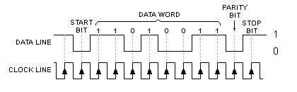
Start bit (start bit) - the bit indicating the start of the transfer, usually equal to 0.
Data bits - 5, 6, 7 or 8 data bits. The first bit is less significant.
Parity bit - used to detect errors. It can have the following values:
Oddness (ODD) is such that the number of units in the packet has always been odd
Always 1 (MARK), the parity bit will always be 1
Always 0 (SPACE), the parity bit will always be 0
Not used (NONE)
Stop bit (stop bit) - the bit indicating the end of the packet, can take the values 1, 1.5 (data bit = 5), 2.
For example, 8E1 means that 8 data bits are transmitted, the parity bit is used in EVEN mode, and the stop bit takes one bit.
Flow control in RS-232
In order not to lose data, there is a data flow control mechanism that allows you to temporarily stop data transfer to prevent the boot from overflowing.
There is a software and hardware way of controlling data.
The hardware method uses RTS / CTS pins. If the transmitter is ready to send data, it sets the signal on the RTS line. If the receiver is ready to receive data, it sets the signal on the CTS line. If one of the signals is not set, no data transfer will occur.
The software method uses the Xon and Xoff characters (in ASCII the Xon = 17, Xoff = 19) sent via the same TXD / RXD communication lines as the main data. When data reception is not possible, the receiver sends the Xoff symbol. To resume sending data, the Xon symbol is sent.
How to check the operation of RS-232?
If you use 3 cables, just connect RXD and TXD together. Then all sent data will be received back. If the full RS-232 interface is used, then the following combinations must be combined: